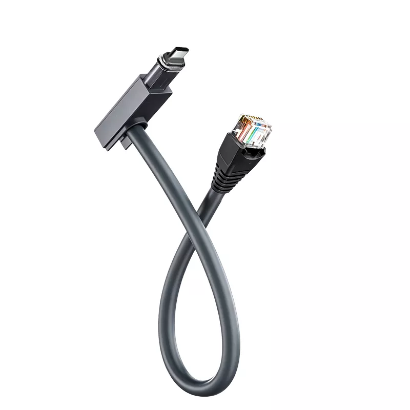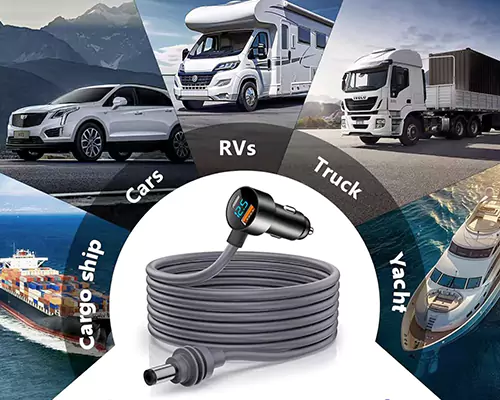

Yes—but the Anderson connector alone doesn’t make the system compatible. Your battery or DC supply must deliver the voltage and current required by the specific Starlink terminal, and the adapter must have the correct output connector, polarity and power path. If the source voltage doesn’t match the terminal input, you need a DC-DC converter rather than a passive cable.
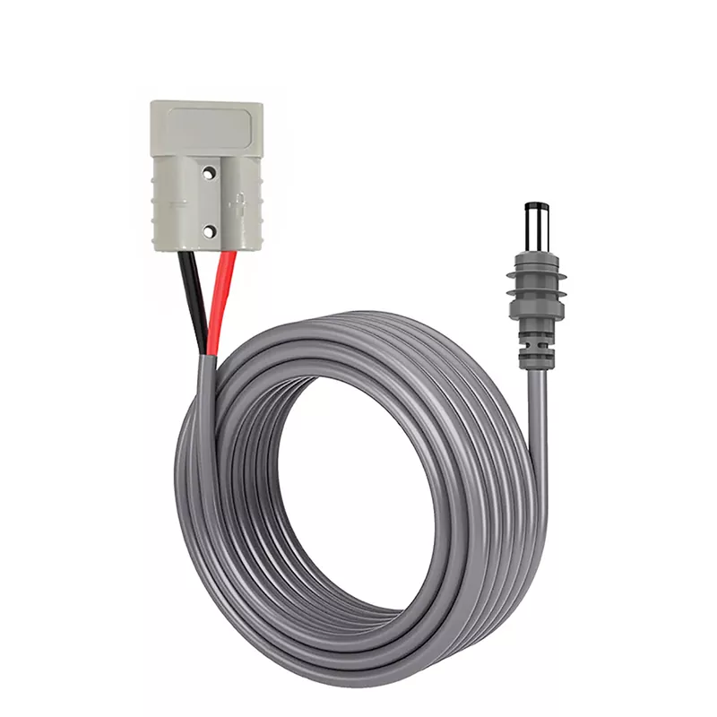
An Anderson Powerpole is an electrical connection, not a voltage standard. Two sources can use identical housings while supplying different voltages, current limits or polarity arrangements. That distinction matters because a cable-only Starlink DC to Anderson adapter passes source power through; it doesn’t automatically correct an incompatible supply.
Start with the input requirements printed on the terminal or its approved power equipment. Then check the battery’s actual output range, not just its nominal description. Battery voltage changes with state of charge and charging conditions. The source must also sustain the terminal’s operating demand without excessive voltage drop.
TLD Electronics lists adapter configurations with 10V-30V DC input and selectable outputs. That range describes available product configurations, not permission to connect every 10V-30V source directly to every Starlink terminal. The selected configuration still has to match the intended terminal and installation.
| What you have | What to verify | Likely power path |
|---|---|---|
| Battery output already accepted by the terminal | Connector size, polarity, current capacity and voltage across the battery’s operating range | Passive Anderson cable may be appropriate |
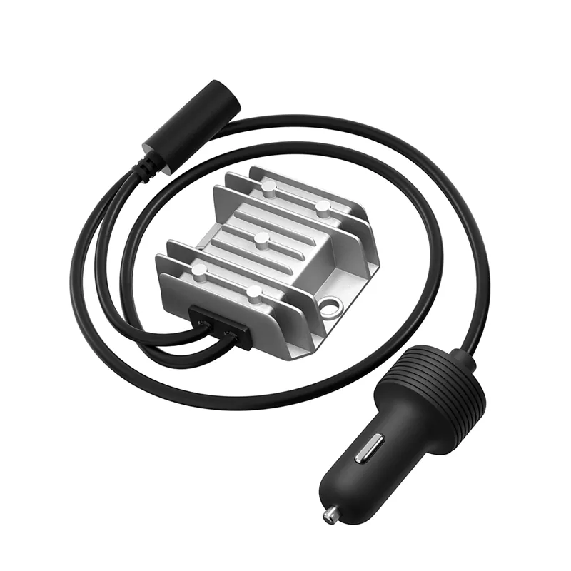
| Battery voltage outside the terminal’s accepted input | Required regulated output and sufficient source capacity | Anderson adapter with a suitable DC-DC converter |
| Starlink system without a documented direct-DC input | Complete power architecture, including any required power supply or data/power hardware | Model-specific conversion system, not an assumed barrel-plug cable |
| Unknown terminal revision or unlabeled third-party cable | Exact model, input specification, pinout and polarity | Stop and document the system before ordering |
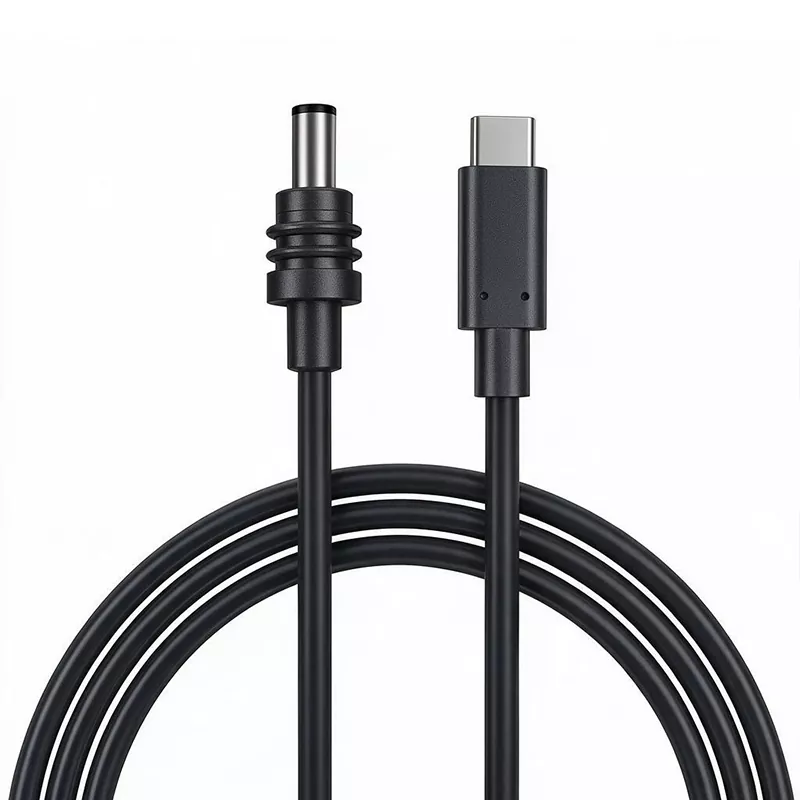
A Starlink Mini installation may support a direct-DC approach, but you still need to verify the requirements for your hardware revision. Don’t order an Anderson Powerpole to 5.5 x 2.1 mm DC cable simply because the plug appears to fit. Barrel connectors with similar dimensions can differ, and physical fit doesn’t confirm polarity or electrical compatibility.
Check the terminal documentation and label, then specify the mating plug dimensions, center polarity and accepted input range. If your 12V or 24V battery system falls outside that range at any point in its charge cycle, use regulated conversion.
Don’t treat a Gen 3 system as though it has the same DC input arrangement as a Mini. Identify every component between the battery and terminal, including the original power supply, router and any equipment carrying both power and data. A connector that fits one device doesn’t establish compatibility with another generation.
For a Gen 3 Anderson power setup, provide the exact hardware version and intended wiring architecture to the adapter supplier. That prevents a common purchasing error: selecting the output plug first and investigating voltage delivery later.
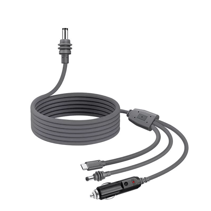
A passive cable is the simpler option. It has fewer conversion components and avoids converter losses, but it offers no protection against choosing the wrong source voltage. The battery, fuse, connectors and conductors must all be suitable for the load.
TLD Electronics offers configurations using 16 AWG copper conductors, Anderson connector options rated at 15A, 30A or 45A, and PVC or TPU jackets. Choose among those options based on the complete assembly and installation conditions. A higher connector rating doesn’t compensate for an undersized conductor, long cable run or incompatible terminal input.
A converting configuration regulates the power presented to the terminal. Depending on the source and required output, that may call for voltage reduction, voltage increase or a converter that can regulate across a changing battery range.
Specify the source’s minimum and maximum operating voltage, the terminal’s accepted input, required output connector and expected continuous load. Converter capacity also needs headroom for startup and changing operating demand. Avoid selecting it solely from a battery’s nominal voltage or a connector’s ampere marking.
The details that look minor on a quote are often the ones that cause field failures. A useful purchasing specification should cover:
TLD Electronics supports standard and custom lengths as well as custom connectors, colors, jackets, packaging and IP-rating configurations. These choices are relevant for RV battery systems, solar installations, marine integration, amateur-radio supply and emergency-communications equipment.
No start: check voltage at the terminal end under load, then verify polarity and the output plug. Correct open-circuit voltage doesn’t rule out a weak supply, blown fuse or high-resistance contact.
Repeated rebooting: suspect voltage sag, inadequate converter capacity, excessive cable length or a battery-management system interrupting output. Measure the system during startup and operation rather than testing only at rest.
Hot connector: disconnect the system and inspect for poor crimping, loose contacts, contamination, damaged housings or a connector rating below the required current. Heat at one contact usually points to resistance at that joint, not a need for a larger battery.
Intermittent power: look for strain near the Anderson contacts and DC plug, incorrect housing engagement, cable damage at pass-through points or moisture intrusion. Replacing the adapter without correcting routing or contact damage often produces the same failure again.
Send TLD Electronics the Starlink model, battery voltage range, required output, connector orientation, polarity, cable length, jacket preference, operating environment and order quantity. Ask for the proposed electrical configuration and sample-testing requirements to be recorded before production.
The company offers factory testing, small batches and OEM cable assemblies, and states ISO 9001, ISO 14001 and IECQ QC 080000 management certifications. Buyers should still define the inspection criteria, packaging, lead time and any required IP configuration for the specific order.
Review the available custom Starlink Anderson adapter configurations or request an OEM quotation. The concise answer remains: an Anderson connection can power Starlink only when the source, conversion method, cable assembly and terminal input are documented as compatible.
-