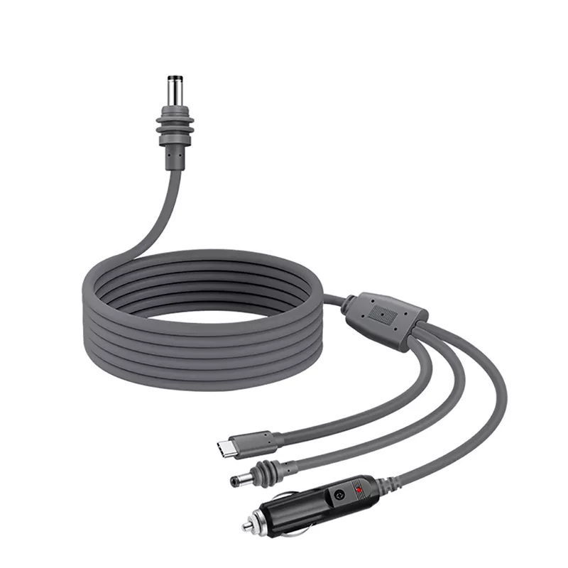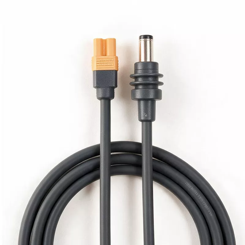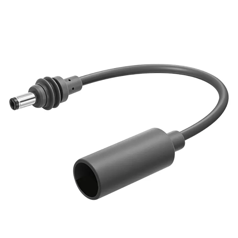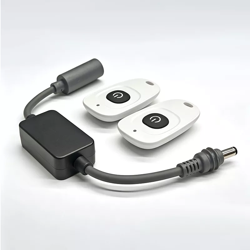

A 433MHz remote control switch lets you turn compatible DC-powered equipment on and off without reaching the power source. An inline receiver sits between the DC supply and the load, while a handheld transmitter sends the command by radio. TLD Electronics offers this product category for 12V and 24V DC systems, with 5.5×2.1mm male and female connectors, a stated rating up to 10A, and a two-button keychain remote.
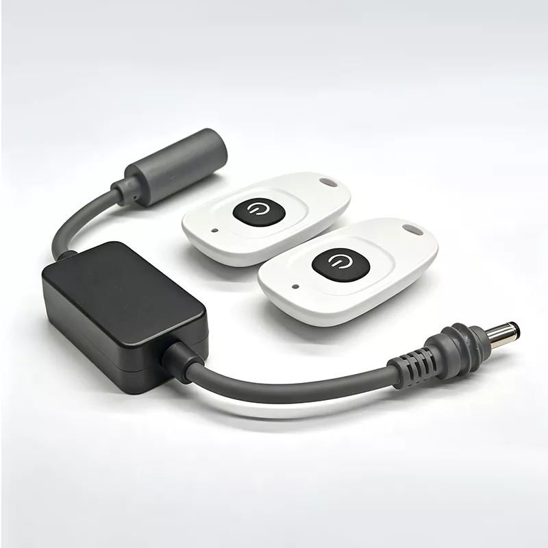
The short answer: it adds wireless on/off control between a DC power source and the connected device
The switch is an adapter with an electrical job, not just a wireless accessory. Connect the DC source to one side and the device to the other. The receiver then controls whether power passes to the load. This arrangement avoids modifying the device itself and can make the installation plug-and-play when the voltage, connector size, polarity, and current demand all match.
A DC Male to Female 433MHz Remote Control Switch is useful where the normal power switch is inconvenient to reach: behind a display, inside a cabinet, under a vehicle panel, or near a pump installed away from the operator. It does not provide speed adjustment, motor reversing, dimming, or process automation unless those functions are separately specified. Its basic purpose is remote power switching.
How the keychain transmitter and inline receiver control power
Pressing a button on the keychain transmitter sends a coded radio-frequency command in the 433MHz band. The inline receiver listens for the paired or recognized signal and changes its internal switching state. One button typically commands on and the other commands off for this two-button format. The load remains connected to the same DC source; the receiver simply determines whether electrical power reaches it.
The coding matters because frequency alone doesn’t identify a particular remote. Many products can operate near 433MHz, so the receiver must recognize the intended transmitter protocol or code. Buyers planning replacements, multiple remotes, or several receivers should ask how pairing works and how many transmitters can be stored. Those details aren’t interchangeable across all 433MHz products.
Also confirm what happens after a power interruption. Some receivers return off, while others restore the previous state or follow a different default. That behavior can be critical for pumps, fans, security equipment, or unattended loads, and it shouldn’t be assumed from the frequency or connector style.
Electrical compatibility depends on more than the 10A rating
A 10A label is only one boundary. The supply voltage, load type, connector contacts, cable conductors, ambient temperature, duty cycle, and startup current can all determine whether the installation is suitable. The safest buying decision is based on the complete current profile of the equipment, not the number printed on its power adapter alone.
Confirm 12V or 24V DC input, connector dimensions, and polarity
This product category is intended for 12V and 24V DC equipment. It isn’t a converter: a 24V source still sends 24V to the connected load when the switch is on. Never use it to make a 12V device operate from 24V, and don’t connect it directly to AC mains.
The stated barrel connector size is 5.5mm outside diameter by 2.1mm inside diameter. That distinction matters because a similar-looking 5.5×2.5mm connector may feel loose, fail to make dependable contact, or not fit correctly. Verify both mating connectors rather than judging by appearance.
Polarity needs the same attention. Many DC products use center-positive wiring, but that isn’t universal and should not be inferred. Compare the source, inline receiver, and load markings or confirm polarity with suitable test equipment. Reversed polarity can prevent operation or damage the receiver and connected device. A 5.5×2.1mm plug-and-play DC remote switch is only plug-and-play when all three interfaces agree.
Check continuous current and startup demand from motors, pumps, fans, and LED drivers
Motors and pumps can draw far more current while starting than they consume after reaching normal speed. Fans have the same issue on a smaller scale. LED drivers may produce a brief input surge as their internal capacitors charge. These events can pit switching contacts, trigger a power supply’s protection circuit, overheat connectors, or cause the receiver to reset even when the normal running current appears acceptable.
Ask for the load manufacturer’s startup, inrush, or locked-rotor data, as applicable. Then compare it with the remote switch’s documented switching capability for that type of DC load. Don’t treat “10A maximum” as permission to run every 10A motor or pump. If the load approaches the limit, a properly selected external contactor or control relay may be more appropriate, with the remote receiver operating the control circuit rather than carrying the full load.
Why a 100-meter open-area range may be shorter after installation
The stated range of up to 100 meters describes open-area conditions, not a guaranteed distance through a building, vehicle, or equipment cabinet. RF range is highly dependent on the installation. Test the final receiver position with the equipment running, since interference and shielding may appear only after nearby electronics are energized.
Walls, metal enclosures, interference, antenna orientation, and receiver placement affect performance
Drywall may cause a modest reduction, while masonry, reinforced concrete, foil-backed insulation, machinery, and sheet-metal cabinets can cut range sharply. Mounting the receiver behind a metal panel can shield the signal almost completely. Nearby radio devices and electrically noisy motors or switching power supplies can also reduce dependable operation.
Keep the receiver away from large metal surfaces when practical, and don’t coil or trap any antenna section against power wiring. Orientation can change reception, so test more than one position. The relevant measure isn’t the farthest distance achieved once; it’s repeatable switching from every location where the operator will actually stand.
Indoor, vehicle, and outdoor installations require different placement and enclosure decisions
Indoors, wall construction and electrical cabinets usually dominate the range decision. In a vehicle, body panels, engine electrical noise, voltage transients, heat, and vibration become concerns. Confirm that the unit is suitable for the vehicle’s electrical conditions rather than assuming every 12V product is automotive-rated.
For outdoor use, don’t interpret an RF range claim as a weather-resistance rating. Unless the supplier documents protection against water, dust, UV exposure, and the expected temperature range, place the receiver in an appropriate enclosure. That enclosure must protect the electronics without surrounding the antenna area with metal that blocks the signal.
Where a plug-and-play DC remote switch fits—and where it does not
Good applications include LED lighting, modest DC fans, compatible pumps and motors, automotive accessories, security devices, home equipment, and small industrial loads. The switch is particularly practical when running a separate control wire would be costly or disruptive.
It’s a poor choice for emergency stops, machine guarding, fire-safety functions, or any circuit where a missed radio command could injure someone or damage equipment. Radio control can be delayed, blocked, interfered with, or activated from an unexpected location. Safety-critical shutdowns need appropriately rated, hardwired controls. The device also isn’t suitable for AC loads, loads beyond its documented switching capacity, or applications requiring proportional control rather than simple on/off operation.
Before ordering: verify the load, polarity, RF documentation, testing evidence, and supplier terms
Use this final check before approving a sample or production order:
- Load: Record the operating voltage, continuous current, startup or inrush demand, and whether the equipment is resistive, inductive, or driven by electronic circuitry.
- Connections: Confirm 5.5×2.1mm dimensions on both sides, correct male-to-female orientation, and matching polarity from source through load.
- RF behavior: Ask about pairing, additional remotes, power-loss behavior, practical range, and the effect of installing the receiver inside an enclosure.
- U.S. documentation: Request the applicable FCC authorization information for the exact keychain transmitter revision being purchased. Don’t accept paperwork for a visually similar remote without checking the model identity.
- Testing: Ask what electrical load, compatibility, and RF range tests were performed and under what conditions. A 100-meter open-area result doesn’t replace testing in your installation.
- Supplier terms: Confirm sample availability, minimum order quantity, lead time, warranty handling, and whether connector, cable, labeling, packaging, or pairing options can be customized.
TLD Electronics serves OEM, wholesale, small-order, and bulk buyers. Its published 433MHz remote switch specifications provide the starting point; your load data and installation conditions determine whether the switch is the right fit.