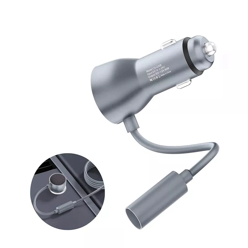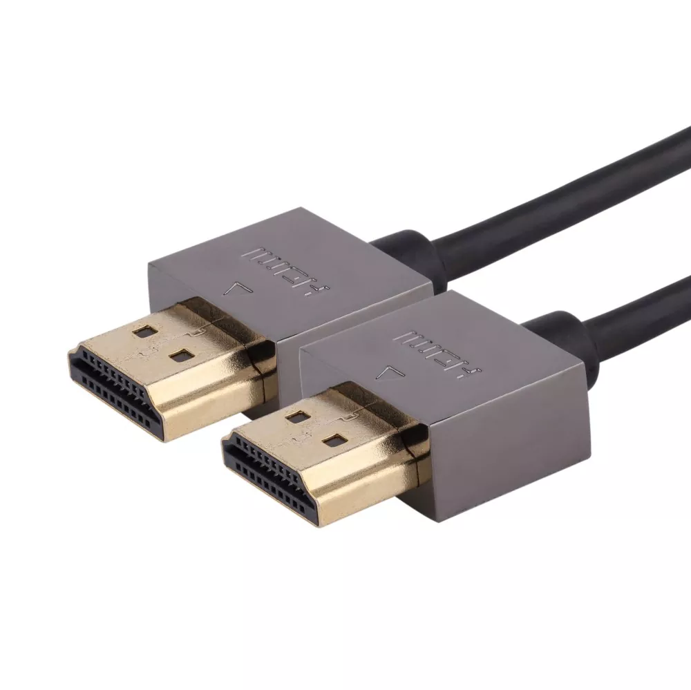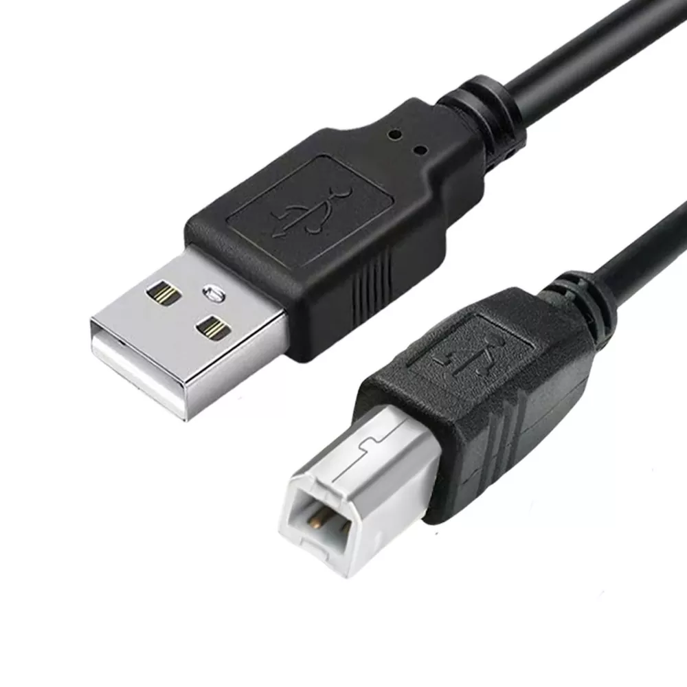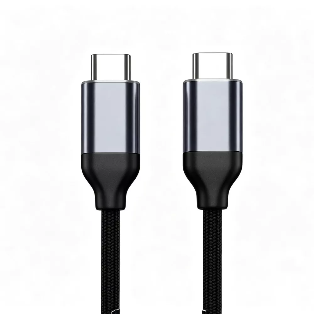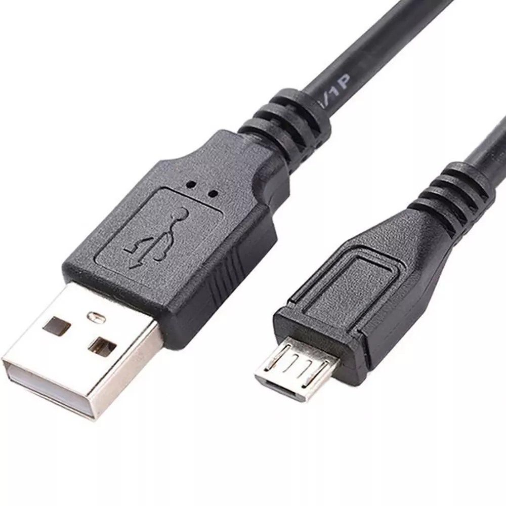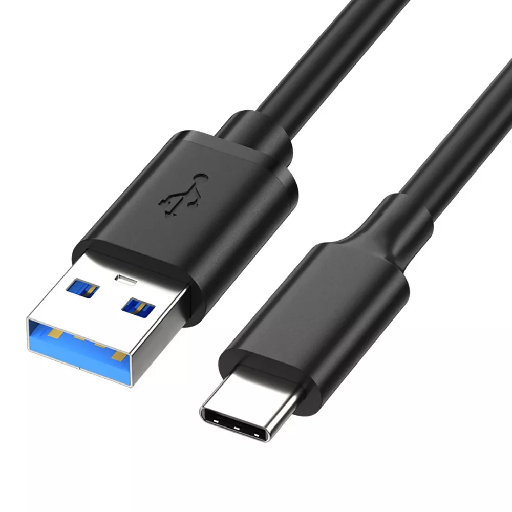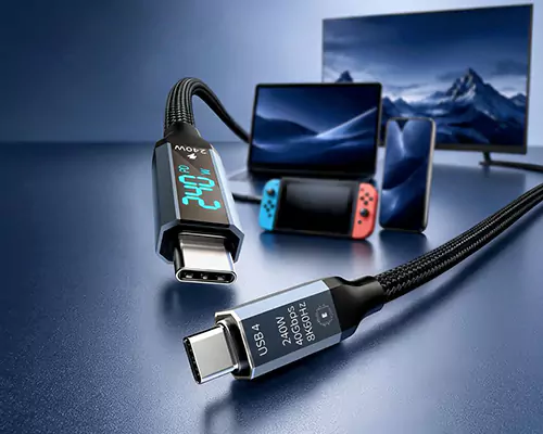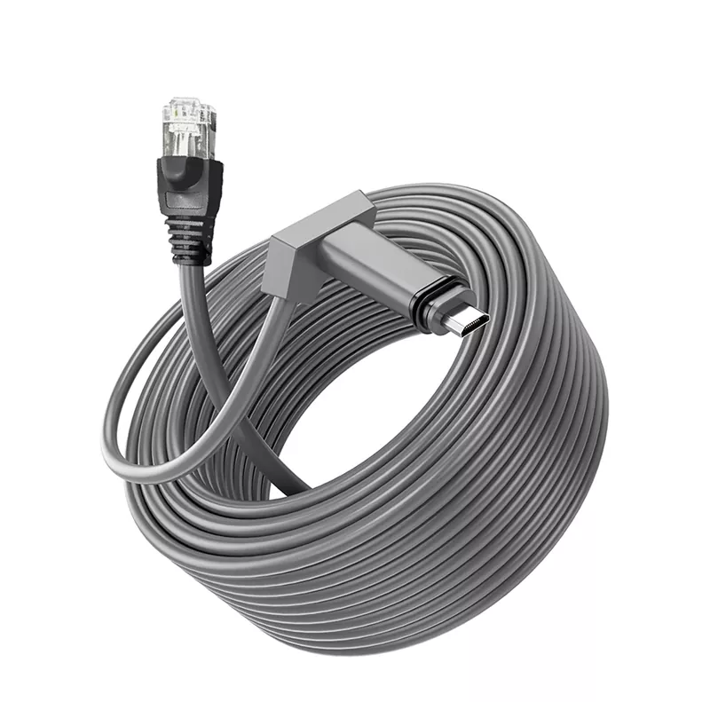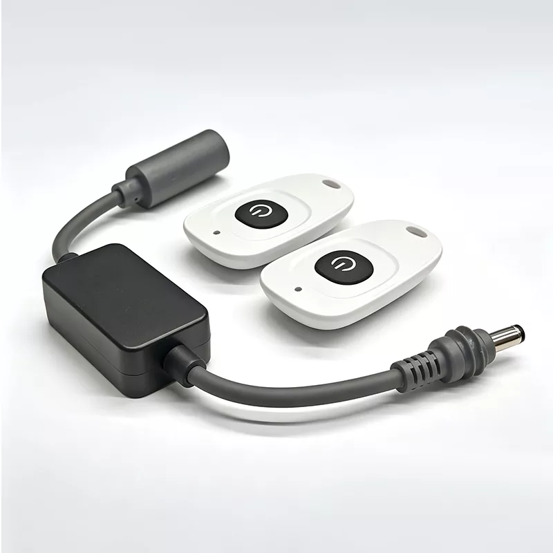

The short answer: it works only when every physical and electrical interface matches
A Starlink DC to XT30 Cable will work only if the terminal connector, XT30 gender, polarity, source voltage, available power and any required voltage conversion all match. An XT30 plug fitting into a socket proves only that the mechanical interface is compatible. It says nothing about voltage, polarity or the source’s ability to sustain the terminal under load.
This distinction matters for a Starlink Mini battery power cable, portable power station connection or RV installation. Product names are often abbreviated, and two assemblies described as “XT30 to Starlink” may perform different jobs. Before ordering a Starlink DC to XT30 cable, verify the complete configuration rather than relying on the connector names in the title.

Map the complete power path before choosing a cable
Start at the power source and trace every interface to the terminal. Record the source model, output port, mating connector, cable, converter if present, terminal plug and exact Starlink hardware version. This catches a common purchasing error: checking the two cable ends while ignoring what happens electrically between them.
A battery pack, solar-storage system and portable power station may all expose XT30 connectors, but those ports aren’t necessarily equivalent. One may be an output, another an input, and another may operate only under certain control settings.
Identify the Starlink terminal input, XT30 gender, mating connector and polarity
Confirm the exact terminal input from the hardware label, manufacturer documentation or the original power lead. Don’t assume every Starlink terminal uses the same DC connection. If the terminal accepts a barrel-style plug, verify the plug dimensions, contact arrangement and polarity. A plug that looks right can still have the wrong inner diameter or fail to seat fully.
XT30 gender also causes avoidable returns. Sellers and buyers sometimes describe gender by the plastic shell rather than the electrical contacts. Compare clear connector photographs and identify which contacts are pins and which are sockets. Then obtain a polarity diagram for both ends. Reversed polarity can cause immediate failure, trigger protection circuitry or leave the terminal completely unresponsive.
Confirm the battery or power-station output and whether voltage conversion is required
Check the source port’s output-voltage range, continuous output rating and operating instructions. The relevant figure is the rating for the specific XT30 port, not the power station’s total advertised capacity. Confirm that the port is genuinely an output and that it remains enabled continuously.
The terminal must receive an acceptable input across normal battery discharge and charging conditions. If the source voltage doesn’t stay within that range, you need a correctly specified DC converter rather than a passive lead. A raw solar-panel output should not be treated like a regulated battery output; use the controlled output provided by the appropriate storage or charge-control system.
Passive and voltage-converting cables are not interchangeable
A passive XT30 cable carries power through conductors and connectors. It doesn’t correct an unsuitable voltage simply because the terminal-side plug fits. A voltage-converting assembly includes electronics intended to regulate, step up or step down the source before power reaches the terminal.
If conversion is required, check the converter’s stated input range, regulated output, continuous load capability, thermal limits and protection behavior against the exact source and terminal documentation. Also ask whether the converter is integrated into the cable or supplied as a separate module. That affects mounting, heat dissipation and weather protection.
The wrong choice produces recognizable symptoms: no startup, repeated rebooting, a power station shutting down, intermittent operation as the battery discharges, or an unusually warm connector. Don’t try to cure an electrical mismatch by ordering a thicker passive XT30 to Starlink Mini DC cable.
Cable length, wire construction and installation conditions can change real-world performance
Longer cable runs increase voltage loss and create more opportunities for damaged joints, loose connectors and abrasion. Wire gauge must therefore be selected for the ordered length, expected load and installation environment—not copied from a much shorter cable. Conductor material, termination quality and connector contact resistance matter as well.
Route planning is especially important in an RV or off-grid setup. Avoid exhaust components, sharp sheet-metal edges, hinge points and locations where water can collect around an inline converter. Specify suitable jacket properties if the cable will face sunlight, oil, repeated flexing or low temperatures. Strain relief should carry movement before it reaches the crimp or solder termination.
Shielding may be available as a custom option, but it doesn’t compensate for undersized conductors, excessive length or poor contacts. For a custom-length Starlink Mini power cable, give the supplier the actual routing length and installation conditions instead of asking for “extra cable just in case.”
Documentation matters for retail purchases, custom assemblies and wholesale orders
A single accessory purchase still needs a clear wiring description. For distributors and OEM buyers, configuration control becomes critical because connector gender, polarity, wire gauge, jacket, length, labels and packaging can all vary under one broad product name.
TLD Electronics offers Starlink power and Ethernet cables, including XT30, XT60, DC barrel, USB-C, battery-pack, portable-power-station, solar, RV and off-grid configurations. Buyers considering a standard or custom Starlink XT30 power cable configuration should put every variable on the drawing, quotation or purchase order.
Request configuration-specific continuity, polarity, connector and electrical-performance test evidence
TLD Electronics describes continuity, polarity, connector and electrical-performance checks as part of production. Ask what those checks cover for your exact assembly and how the ordered configuration is identified in the records.
For wholesale Starlink XT30 power cables, approve a controlled sample or drawing before volume production. The record should distinguish connector variants that share a similar appearance and show the intended source and terminal ends. Packaging labels should preserve that distinction; otherwise, electrically different cables can become mixed during receiving or field installation.
Separate TLD Electronics’ ISO management-system certifications from product-specific compliance claims
TLD Electronics states that it holds ISO 9001, ISO 14001 and IECQ QC 080000 management-system certifications. Those certifications concern management systems and shouldn’t automatically be presented as certification of every finished cable configuration.
If your project requires a product-specific safety, environmental or market-access document, request evidence tied to the exact ordered construction. A change in connector, wire, jacket, converter or packaging can affect which documents apply. This is particularly important for OEM programs and regulated distribution channels.
Final ordering checklist for portable power stations, battery packs, solar storage and RV systems
- Identify the exact Starlink terminal model, hardware version and power-input connector.
- Confirm the XT30 port is an output and identify its contact gender from the contacts, not the shell.
- Match polarity at both ends using drawings or documented pin assignments.
- Check the source port’s output range and continuous rating, not only the device’s total capacity.
- Determine from source and terminal documentation whether the cable can be passive or must include voltage conversion.
- Specify cable length, wire gauge, jacket, routing conditions, strain relief and any required weather protection.
- For solar use, connect through an appropriate controlled power source rather than assuming a panel output is suitable.
- Request configuration-specific continuity, polarity, connector and electrical-performance test evidence.
- For custom, OEM or wholesale orders, approve the drawing, sample, labeling and applicable product documents before production.